CUSTOMER: VICUSDT
RELATED SERVICES: PROPELLER DESIGN
SOFTWARE:PropCAD® and Rhinoceros®.
SCOPE OF WORK:
- Technical data collection: Main propeller data
- Analysis of cloud of points measured by laser scanner
- Create preliminary propeller
- Fit surface blade propeller to cloud of points
- Create manufacturing drawing
METHODOLOGY:
The geometric reconstruction of the blade propeller is carried out in four different steps:
1- Measurements of Cloud of Points: A blade propeller was measured by a laser scanner to get cloud of points. The cloud of points was measured with a density to achieve a point for each 1 x 1.5 cm2. A local coordinate system was set for the laser scanner respect to the hub to have a flat surface and shaft axis as reference for the cloud of points.
2- Preliminary blade propeller: A preliminary blade propeller was created using the technical main data and some measurements made by hand, such as: chord, pitch, thickness. The radial distributions of these parameters were smoothed to avoid the occurrence of bumps or bumped surfaces over propeller blade.
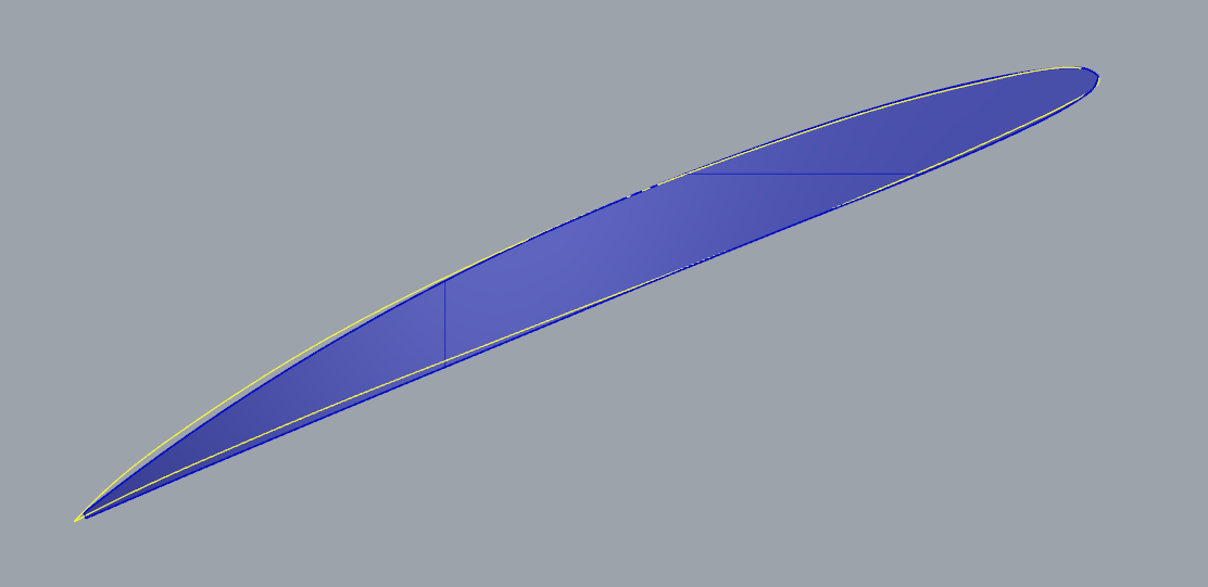
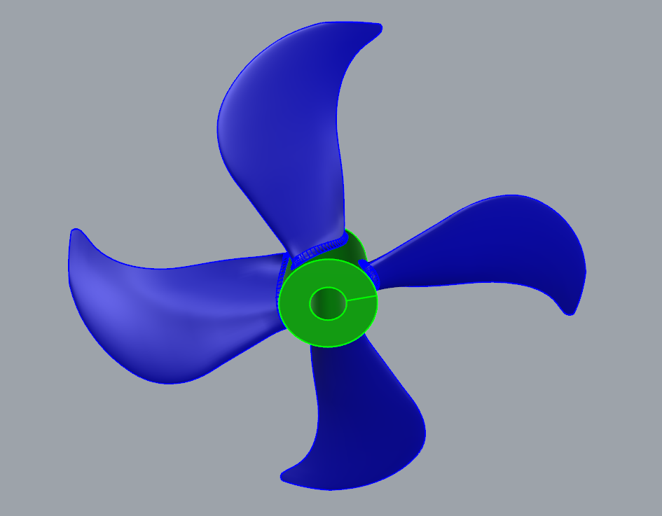
3- Final blade propeller: Before of proceeding to modify the preliminary blade, the cloud of points were studied and analysed to define several surfaces at different radii and determine the blade section shape. The final blade propeller was generated taking as basis the preliminary blade propeller, defined previously, with the new blade section shape and fitting the blade surface to the cloud of points.
4- Manufacturing drawing: Once the final blade propeller is done, the manufacturing drawing is created to manufacture it.