There are different aspects concerning purely boat drag or resistance in which CFD (Computational Fluid Dynamics) can bring a good added value for planing crafts.
Apart from determining boat resistance and dynamic trim and sink (or rise), there is value in assessing CG for ship performance optimization at a specific range of Froude. Ship resistance can be modified by properly locating CG which plays a role in the shape of the resistance curve both in preplanning and planing speeds. we briefly describe below these topics.
Contenidos
Boat resistance in planing craft
 CFD Is actually computing the hydrodynamic forces over the hull, this is more accurate than relying on analytical power prediction methods which are limited to certain geometric parameters of a prismatic type hull. There have been good improvements to the Savitsky method through the years, but these methods have their time and place within the project. But When the hull has some additional particularities going with a detailed CFD analysis carried out by experts can give you the extra mile. At a stage where the ship is going to be built and the power plant selected, CFD provides an accurate assessment of the hull features. For each speed, the calculation provides sink and trim, which is quite useful, as well as these parameters, can be easily compared to sea trials for validation purposes.
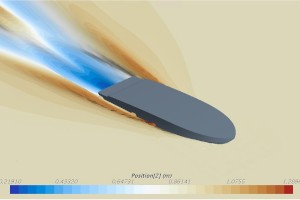
Spray rails and wetted surface
Spray rails location to minimize wetted surface can be accurately decided and resistance reassessed with little cost for the designer. High-pressure areas can be identified and quantified at the desired speed, so the designer can use that information, for instance, in the structure design (even though class society or ISO rules apply).
Assessing Center of Gravity
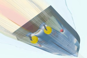 Location of CG is really important because it affects the steepness of the resistance curve and CG parametric assessment is easy and cost-effective with CFD. In a typical V bottom monohull, the further aft the CG, the higher the hump (in transition to planing) but the lower the resistance in planing mode. Contrarily, the fore the CG the lower the hump but the higher the resistance in planing mode. This is of vital interest in order to determine where the boat is performing best. Is the boat being designed for top speed? or instead is service speed in planing mode the focus of interest? With CFD, feedback on this matter is quite straightforward.
Similarly, knowing the effect of the boat weight on-resistance is critical. It is not unusual that throughout the design loop weight changes. CFD can help to determine resistance in different weight scenarios with little cost for the designer or shipyard.
By parametrically assessing these two parameters, most of the time the use of trim tabs (to control behavior in the hump) can be disregarded making a cleaner design.
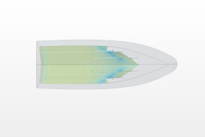
Planing mode
Instead of relying on Froude number or even in CG vertical movement (z-axis) when given, planning mode is better determined by assessing hydrodynamic vs hydrostatic forces over the hull and the contribution of each one. With CFD this is monitored for every speed under analysis.
Next time you are facing the design stage of your planning boat you can consider these aspects and how they can be easily incorporated into your project.
