Ship propulsion engineering
Shaftline analysis and design for marine propulsion systems
Comprehensive shaftline analysis and propeller shaft design solutions to ensure maximum propulsion efficiency and mechanical reliability in any marine vessel.
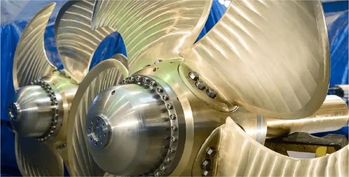
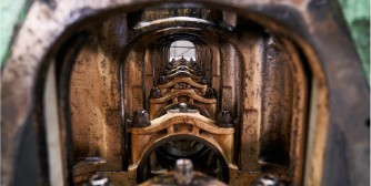
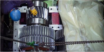
A good performance of the propulsion can only be achieved if every component is well studied.
Shaftline design includes not only the sizing of the shaft, but its behavior under different load conditions in operation, including the various vibration modes of the system.
All the calculations for your shatfline
VICUSdt has a significant experience carrying out all the necessary shafting calculations for every type of propulsion shafting system for the most important Classification Societies and shipyards all over the world. Our reference list include every type of ship and propulsion configuration. It doesn’t matter if your project is retrofitting or newbuild, or if it is fitted with a direct drive or reduction gear, diesel or electric motor, thrust bearing, shaft brackets, oil or water stern tube, or any other feature. We definitely can help you with all the required shafting calculation and sea trial measurements for a detail evaluation.
Shaft alignment and vibration control
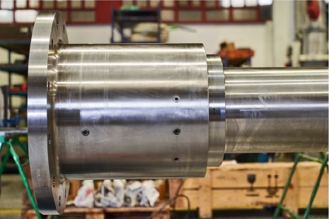
Misaligned shafts and unaddressed vibrations can lead to serious failures in marine propulsion systems. Our shaft alignment services prevent misalignment between engine, shaft and bearings, while our vibration analysis ensures that your shaftline runs below critical resonance frequencies. Together, they guarantee long-term durability.
“Control alignment and vibration in your shaftline to avoid costly damages”
Smart shaftline design adapted to your project
Effective shaftline design involves not just correct sizing, but also load balancing, optimal bearing layout, and minimizing torsional and lateral vibrations. We adapt the shaftline to each vessel’s propulsion layout, whether it requires high-load support or minimal weight, reducing project costs and increasing efficiency. Sometimes, preliminary calculations should take place in the first stage of a project to make decisions about the number of bearings and their position as this can impact the project cost significantly.
Propeller shaft alignment process
Not only for newbuilding, but also in retrofitting projects, shaft alignment calculation takes into account the characteristics of the shaft, the propeller and the hydrodynamic along with bearings particulars, gearbox elements and applied forces and flexible couplings in order to evaluate crucial aspects for the alignment:
- Loads share between bearings, and optimal positioning during alignment.
- Shaft slope (particularly in the aft-most bearing)
- Stress and deflection along the shaft
Alignment indications (bearing offsets, gap and sag values, jack-up instructions and expected load values) are given for a correct alignment procedure onboard.
Whirling, axial vibration analysis for your shaftline
Avoid failures caused by resonance or instability with accurate whirling and axial vibration analysis. Our engineers determine the natural vibration frequencies of your shaftline and verify they stay clear of operational speeds, protecting your vessel from fatigue and mechanical damage.

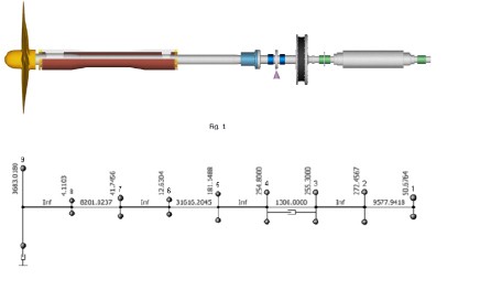
Torsional analysis: avoid critical issues in your shaftline
Torsional vibration and stresses under variable load conditions must be calculated to prevent fatigue failures. Our finite element models simulate shaftline behavior under real operational modes, ensuring your design withstands torque fluctuations and dynamic loads without risk of failure.
