NUMERICAL VALIDATION OF FRANCIS HILL CHART
CUSTOMER: BALIÑO
RELATED SERVICES: CFD SIMULATION INDUSTRY
SCOPE OF WORK:
- Technical data and operational collection:
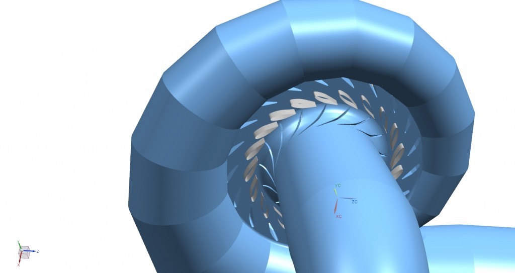
- 3D generation of turbine geometry (spiral case, static and guide vanes, runner and draft tube)
- Collection of operational points to study
- CFD analysis of Francis turbine on each operation point
- Analysis of results
RESULTS:
The flow and pressure figures to define the boundary conditions of the simulation were obtained from points of hill chart (N11 and Q11) and runner rotation speed. Simulation results, time-space average of torque and velocity field and pressure at the inlet and outlet of the turbine, allowed to obtain the net power and the shaft power to calculate turbine efficiency.
Reynolds Averaged Navier Stokes equations (RANSE) along with a turbulence model with law wall were resolved in each simulation. The system of equations is closed with the boundary conditions: total discharge t inlet of spiral casing and pressure at outlet were specified; all other parts were considered as a wall with no slip condition. All flow variables were initialized to zero. Spiral case, static vanes, guide vanes and draft tube were modelled as stationary components whereas the runner was modelled as rotating using a sliding mesh approach in time.
The results, shown in the table, indicate a good agreement between the experimental and numerical values. The differences in efficiency are less than ± 1% at all points analyzed. Therefore, it is concluded that the model is valid for numerical analysis and the study of Francis turbines.